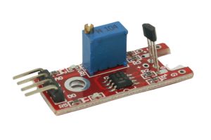
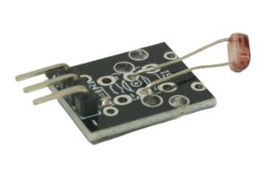
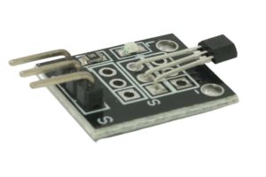
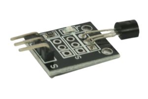
The Linear Hall Sensor Module is a versatile sensor capable of detecting changes in the magnetic field’s strength along a linear path. It is based on the Hall Effect principle and can be used for position sensing, linear displacement measurements, and other applications that require precise magnetic field detection. In this step-by-step guide, we’ll show you how to set up the Linear Hall Sensor Module with an Arduino and create projects that leverage its magnetic sensing capabilities.
Materials Needed:
- Arduino board (e.g., Arduino Uno, Arduino Nano)
- Linear Hall Sensor Module (e.g., A1302)
- Magnet (e.g., a small neodymium magnet)
- Resistor (10k ohms)
- Breadboard and jumper wires
- USB cable for Arduino
- Computer with the Arduino IDE installed (https://www.arduino.cc/en/software)
Step 1: Wiring
Connect the Linear Hall Sensor Module to the Arduino board as follows:
- Connect the module’s VCC (Voltage) pin to the 5V pin on the Arduino.
- Connect the module’s GND (Ground) pin to the GND pin on the Arduino.
- Connect the module’s OUT (Output) pin to an analog input pin on the Arduino (e.g., A0).
- Place a 10k ohm resistor between the VCC pin on the module and the OUT pin on the module.
Step 2: Arduino Code
Open the Arduino IDE and create a new sketch. Then, enter the following code:
const int hallSensorPin = A0; // Analog pin connected to the Linear Hall Sensor module

void setup() {
  pinMode(hallSensorPin, INPUT); // Set the Hall Sensor pin as INPUT
  Serial.begin(9600); // Initialize serial communication for debugging (optional)
}

void loop() {
  int hallValue = analogRead(hallSensorPin); // Read the analog value from the Linear Hall Sensor

  // Display the Hall Sensor value on the Serial Monitor
  Serial.print("Hall Sensor Value: ");
  Serial.println(hallValue);

  // Add your custom actions or functions here based on the sensor readings.

  delay(100); // Add a small delay to avoid rapid repeated detections
}
Step 3: Uploading the code
Connect your Arduino board to the computer using the USB cable and select the appropriate board and port from the Arduino IDE. Then, click the “Upload” button to upload the code to the Arduino.
Step 4: Observing Magnetic Sensing
Once the code is uploaded successfully, open the Serial Monitor from the Arduino IDE (Ctrl + Shift + M). The Serial Monitor will display the analog values from the Linear Hall Sensor, representing the magnetic field’s strength at the sensor’s location.
Step 5: Experiment and Utilize
Now that the Linear Hall Sensor Module is set up and providing magnetic field strength readings, you can experiment with different magnet placements and distances from the sensor. Adjust the code to create position-sensitive projects, linear displacement measurements, or any application that requires precise magnetic field detection.
Congratulations! You’ve successfully set up and used the Linear Hall Sensor Module with Arduino. This powerful sensor allows you to detect magnetic field changes along a linear path, enabling precise measurements and position sensing. Have fun experimenting and incorporating the Linear Hall Sensor Module into your Arduino projects to harness the power of magnetic precision!

