Want to try a small electronics project without complicated circuits? In this beginner tutorial, we’ll build detect rain using arduino and rain sensor module. You’ll connect one sensor, upload a short Arduino IDE sketch, and see the result. No Wi-Fi account or cloud service is required.
What does it do?
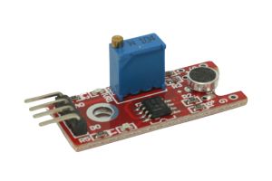
Water droplets bridge the conductive traces on the rain plate. The attached comparator board creates a digital wet/dry signal that Arduino reads.
Parts you’ll need
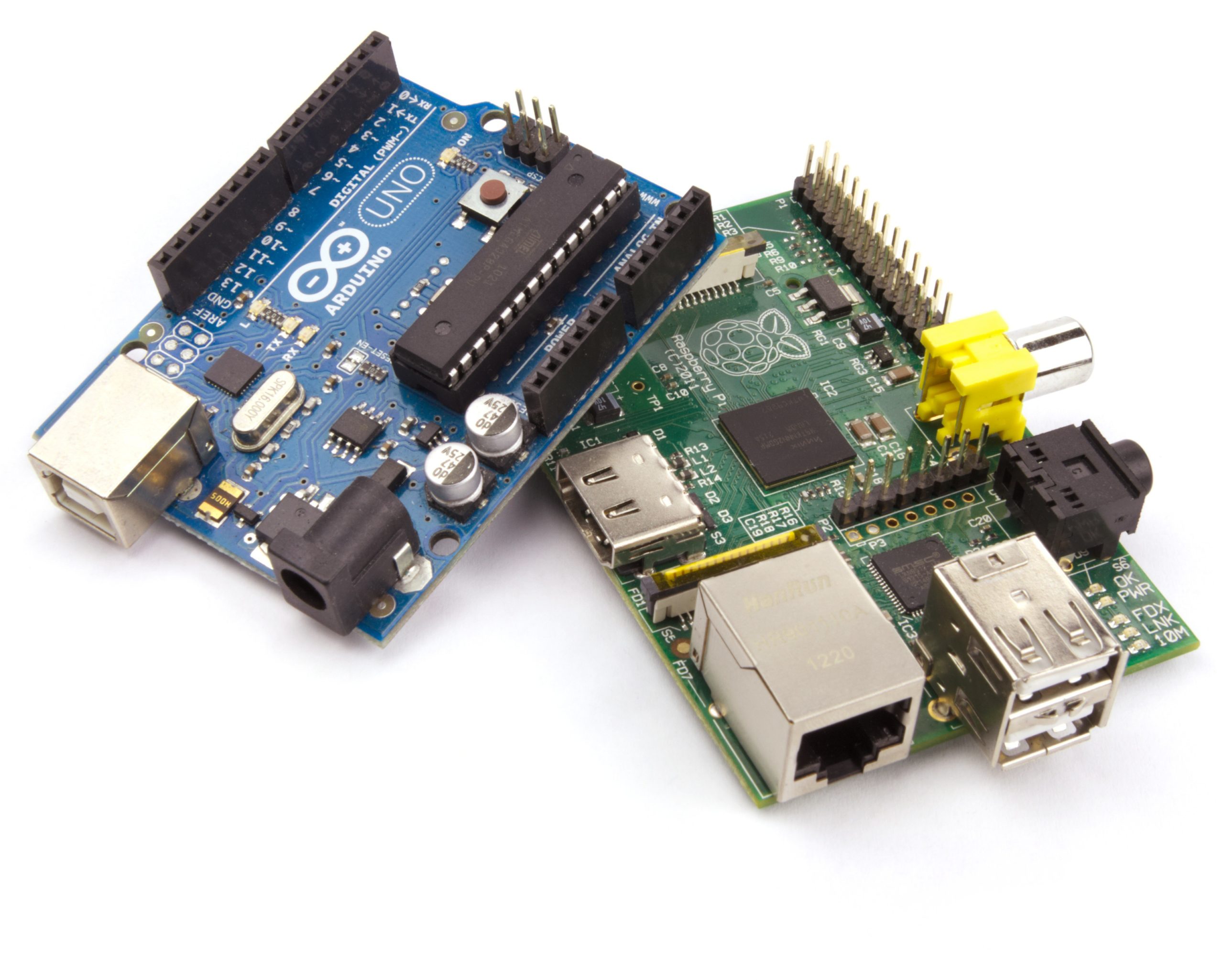
Arduino Uno, rain sensor plate with comparator module, jumper wires. You will also need a computer with the free Arduino IDE installed.
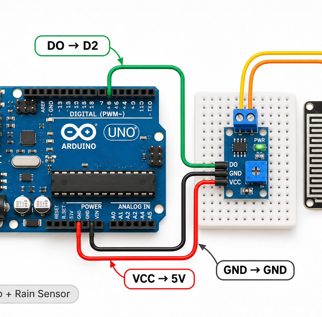
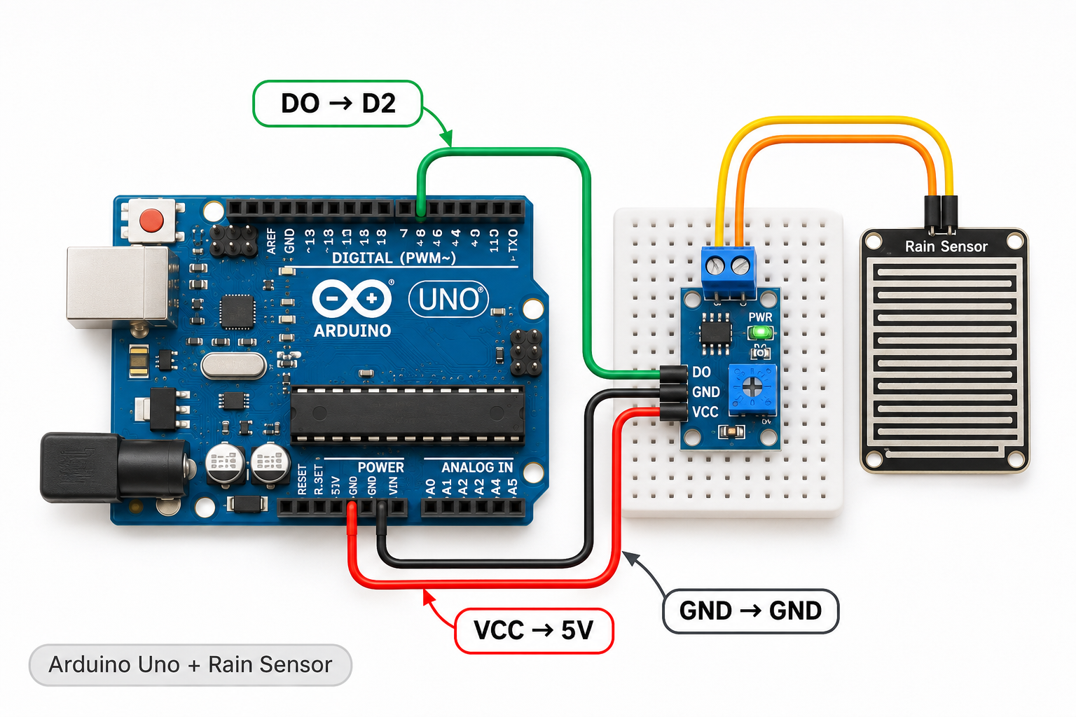
Wiring connections
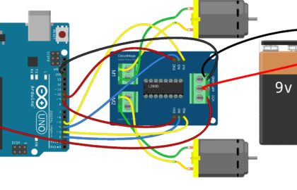
Disconnect USB power before moving any wires. Make these connections carefully:
| Sensor / component pin | Connect to |
|---|---|
| Module VCC | 5V |
| Module GND | GND |
| Module DO | D2 |
| Sensor plate | 2-pin connector on module |
Important: ESP32 GPIO pins work at 3.3V. Do not connect a 5V output directly to an ESP32 input. Board and sensor-module pin labels vary, so double-check the markings on your hardware.
Arduino IDE code
Select the correct board and USB port in Arduino IDE, paste the complete sketch below, and click Upload.
const int rainPin = 2;
void setup() {
  Serial.begin(9600);
  pinMode(rainPin, INPUT);
}
void loop() {
  int state = digitalRead(rainPin);
  Serial.println(state == LOW ? "Rain detected" : "Plate dry");
  delay(400);
}
Expected result
Add a few drops to the plate: Rain detected. Open Tools → Serial Monitor and set the baud rate shown in Serial.begin() in the sketch.
Troubleshooting
Many comparator modules output LOW when wet, but some differ. Turn the threshold potentiometer and verify with the module’s indicator LED. Avoid leaving inexpensive plates wet for long periods because corrosion can occur.
If nothing appears, first check the USB cable, correct board and port, sensor power and ground, and the Serial Monitor baud rate. Recheck every wire against the connection table before changing code.
What to try next
Once this simple example works, try changing the measurement interval or using the sensor reading to control an LED. This is an easy way to learn inputs, outputs, and basic programming.
For more hands-on electronics tutorials, explore CircuitMagic. If you later want to control Arduino or ESP32 projects from a phone over Bluetooth, see our BLE Controller app tutorial. This project itself does not need Bluetooth.