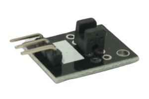
The Light Blocking Module, also known as a Photo Interrupter or Slotted Optical Sensor, is a sensor that detects changes in light intensity caused by the interruption of a beam of light. It consists of an infrared LED and a phototransistor, making it ideal for detecting objects or obstacles in automated systems, security applications, and even for building simple optical counters. In this step-by-step guide, we’ll show you how to set up the Light Blocking Module with an Arduino and create projects that react to the presence or absence of light.
Materials Needed:
- Arduino board (e.g., Arduino Uno, Arduino Nano)
- Light Blocking Module (Photo Interrupter)
- Resistor (220 ohms or 10k ohms, depending on the module)
- Breadboard and jumper wires
- USB cable for Arduino
- Computer with the Arduino IDE installed (https://www.arduino.cc/en/software)
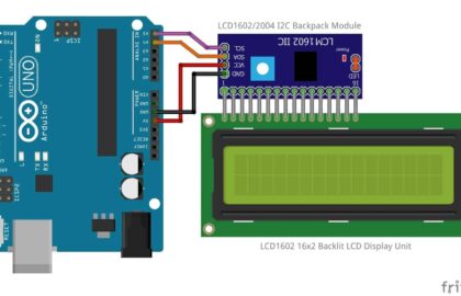
Step 1: Wiring
Connect the Light Blocking Module to the Arduino board as follows:
- Connect the module’s VCC (Voltage) pin to the 5V pin on the Arduino.
- Connect the module’s GND (Ground) pin to the GND pin on the Arduino.
- Connect the module’s OUT (Output) pin to a digital pin on the Arduino (e.g., D2).
- Place a resistor (220 ohms or 10k ohms) between the VCC and OUT pins on the module (choose the resistor value based on the specifications of your module).
Step 2: Arduino Code
Open the Arduino IDE and create a new sketch. Then, enter the following code:
const int blockingSensorPin = 2; // Digital pin connected to the Light Blocking Module's OUT pin

void setup() {
  pinMode(blockingSensorPin, INPUT); // Set the blocking sensor pin as INPUT
  Serial.begin(9600); // Initialize serial communication for debugging (optional)
}

void loop() {
  int blockingState = digitalRead(blockingSensorPin); // Read the state of the Light Blocking Module

  if (blockingState == LOW) {
    Serial.println("Light blocked!"); // Display a message when the light is blocked
    // Your custom actions or functions can be added here.
  } else {
    Serial.println("Light not blocked."); // Display a message when the light is not blocked
  }

  delay(100); // Add a small delay to avoid rapid repeated detections
}
Step 3: Uploading the code
Connect your Arduino board to the computer using the USB cable and select the appropriate board and port from the Arduino IDE. Then, click the “Upload” button to upload the code to the Arduino.
Step 4: Observing the Light Blocking
Once the code is uploaded successfully, open the Serial Monitor from the Arduino IDE (Ctrl + Shift + M). The Serial Monitor will display “Light blocked!” whenever an object blocks the light falling on the sensor. It will show “Light not blocked.” when the light is not obstructed.
Step 5: Experiment and Interact
Now that the Light Blocking Module is set up and responding to changes in light, you can experiment with different objects or surfaces to block the light. Adjust the code to trigger various actions or events in response to the light being blocked or unblocked. You can use this sensor in automation, object detection, and many other applications.
Congratulations! You’ve successfully set up and used the Light Blocking Module with Arduino. This versatile sensor allows you to detect the presence or absence of light, making it useful for various object detection and automation projects. Have fun experimenting and incorporating the Light Blocking Module into your Arduino projects to block the light and trigger interactions!

