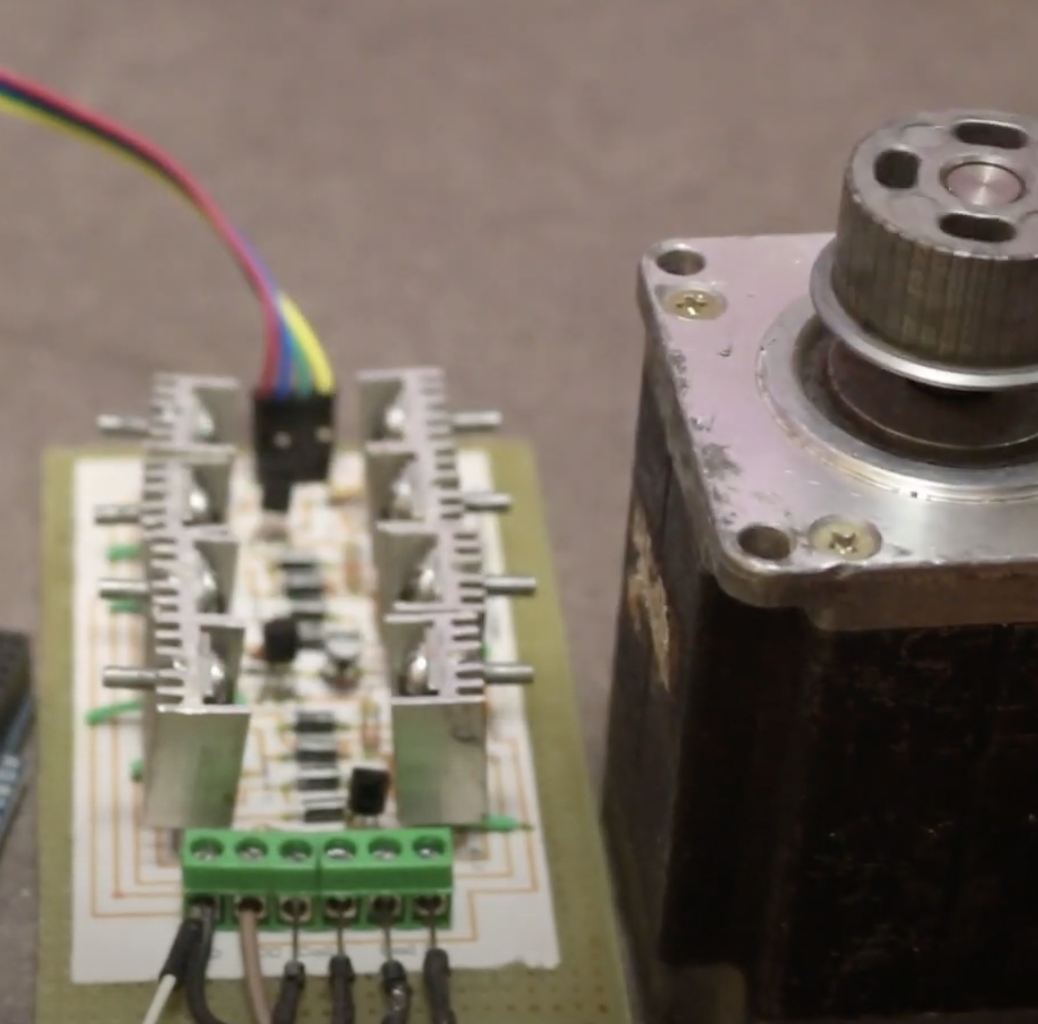
Hi Folks, In this post, I am sharing with you the whole details of my 5 Amp stepper motor driver project which I build and test last week. This driver module I build to run my 22kg high torque stepper motor and I used Arduino to give the commands.
In this article, you will learn…
- How to build 5 Amp stepper motor driver.
- How to run stepper motor with Arduino using driver module.
To make this driver I designed h-bridge circuit and I used TIP-122 and TIP-127 Mosfet. You can find the complete list of components below.
List of components for h-bridge stepper driver module
- Mosfet Tip-122 (4 pcs)
- Mosfet Tip-127 (4 pcs)
- Transistor 2222A (4 pcs)
- Diode 4007 (8 pcs)
- Resistor 10K (4 pcs)
- Resistor 1k (4 pcs)
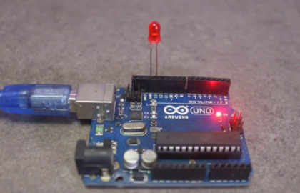
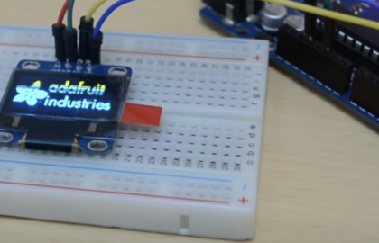
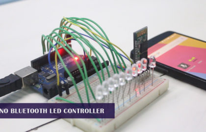
Video demo to run stepper motor with driver and Arduino
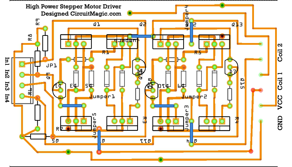
PCB design to make 5amp driver module
Breadboard driver circuit diagram

Arduino code to test stepper motor driver
#include <Stepper.h>

const int stepsPerRevolution = 200;  // change this to fit the number of steps per revolution
// for your motor

// initialize the stepper library on pins 8 through 11:
Stepper myStepper(stepsPerRevolution, 8, 9, 10, 11);

void setup() {
  // set the speed at 60 rpm:
  myStepper.setSpeed(60);
  // initialize the serial port:
  Serial.begin(9600);
}

void loop() {
  // step one revolution  in one direction:
  Serial.println("clockwise");
  myStepper.step(stepsPerRevolution);
  delay(500);

  // step one revolution in the other direction:
  Serial.println("counterclockwise");
  myStepper.step(-stepsPerRevolution);
  delay(500);
}


It looks like you’re using the power rails of the breadboard for VCC and GND but your breadboard circuit isn’t connected to VCC on the breadboard. Only the ground rail. I figured out from the PCB design that you are connecting to ground through the resistor on the base pin of the 2222, and in1-in4 connect to the base of the 2222. From the video, it looks like jumper 6 on the PCB design is supposed to be connected to the middle pin of the mosfet, but your PCB design doesn’t show the jumpers from the GND and VCC rails. I’m trying to use your breadboard circuit in a class project but I’m missing something. Where do I connect the breadboard circuit to VCC?
Thanks for total things
Hello.
I want to build a discrete mosfet driver, do you have a circuit available for yours?
hi can you send 8 amps 120vac drive circuit diagram